Lateral connection joint
Description
Perforated Cable Trays with rimmed ribs PFLR type are designed and manufactured in accordance with the standard CEI EN 61537 Class 23-76 and can be manufactured made of:
- carbon steel S235JR (reference standard UNI EN 10025) hot dip galvanized after working according to ISO 1461
- stainless steel AISI 304
- stainless steel AISI 316
- sendzimir S250GD Z200 (reference standard UNI EN 10147).
Perforated cable trays with rimmed ribs PFLR type are obtained by cold-profiling of coils.
Bending radii of special pieces take into consideration the CEI 11-17 standard, which settles the minimum bending radius according to cable’s diameter; on request, we can supply different bending radii.
Standard covers are plane type and 1.00 mm thick.
On request, higher thickness can be manufactured as well as flowing type covers.
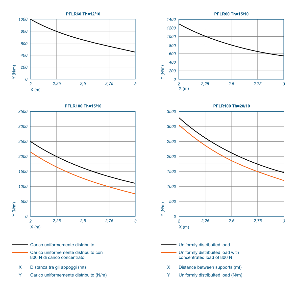
Perforated Cable trays with rimmed ribs PFLR type have been tested through strict tests, to define the maximum admissible load (SWL – Safe Working Load) in compliance with the CEI EN 61537 standard; please find please find herewith enclosed the diagrams which define, according to the distance between supports, the maximum admissible distributed load (UDL – Uniformly Distributed Load) and the maximum admissible load considering an additional concentrated load (CL – Concentrated Load).
As concentrated load we consider a load of 800 N added in the middle span with respect to the supports.
The CEI EN 61537 standard states that the maximum acceptable longitudinal inflexion is 1/100 of the distance between supports, and that the maximum acceptable transversal one is 1/20 of tray width; the inflection of Perforated Cable trays with rimmed ribs PFLR type under load (UDL) falls within these parameters.
Perforated Cable trays with rimmed ribs PFLR type have been tested to verify the electrical continuity in accordance with CEI EN 61537 standard.
The test consists in the passage all along the elements of a 25A electric current, with a frequency between 50 and 60 Hz; the voltage drop must be measured both through the joint and on the whole tray, therefore:
- between two points, 50 mm away from each side of the joint;
- between two points, on one side 500 mm away from the joint.
The measured impedances shouldn’t exceed 50 mΩ through the joint and 5 mΩ per metre without the joint.
The test has been carried out on two straight elements connected by one joint fixed by 8 cup square screws M6x12.
ADDRESS
Uff. Amm.vi e Stabilimento: Via Finati, 6 - 44124 FERRARA – ITALY
PHONE
Informative
We and selected third parties use cookies or similar technologies for technical purposes and, with your consent, also for other purposes as specified in the cookie policy. If you close this banner by ticking or clicking on "Decline", only technical cookies will be used. If you want to select the cookies to be installed, click on "Customize". If you prefer, you can consent to the use of all cookies, including those other than technical, by clicking on "Accept all". You can change your choice at any time.